
Updated: 16-Jul-2026
Looking for factory-style electrical connectors? Tap here.
![]() How to read Volkswagen current flow wiring diagrams
How to read Volkswagen current flow wiring diagrams
Fuse & Relay Panel
General Info
The Bentley Service Manual has numerous errors in its list for relays and fuses. Most of those errors have been corrected here! However, it's wise to verify your relays using the relay part numbers listed below, especially for the 1980-1982 cars. Fuse & Relay Panel.
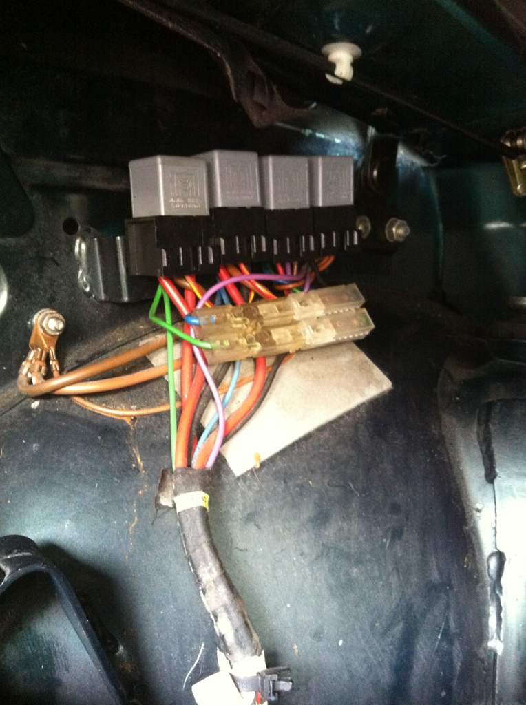
The fuse/relay panel is located under the dash, driver's side, behind the kneebar.
- 1980-1982 fuse/relay panel part number: 171941821C
- 1983-1993 fuse/relay panel part number: 171941821D
IMPORTANT NOTES:
- 1983-1993 fuse amperage:
- Green = 30
- Yellow = 20
- Blue = 15
- Red = 10
- 1980-1982 Cabriolets use ceramic fuses; their amperage is listed on the diagram.
- 1980-1982 fuel pump relay: Originally installed in position L; due to a recall, the relay should have been moved to position 1 with a wiring loom bridge to position L.
- If your car has factory-installed heated seats, the relays for this option are under each front seat.
- If your car has a factory-installed 2-stage after-run cooling fan system ('88+), the relay for this fan is mounted to the left front fender.
- If your car has factory-installed power windows, there is a control unit beneath the dash on the passenger side.
- If your car has a factory-installed power top/roof:
- There is a covered thermo-fuse above the relay panel
- There are 4 relays (control units) inside the trunk, left side
- About 90% of the wiring diagram in the Bentley Service Manual does not reflect what is in the car
- If your car has factory- or dealer-installed daytime running lights, there is most likely a relay attached to the top of the panel (not shown in the diagrams).
- ALL 1983-1993 Cabriolets are CE1
- List of DIN electrical terminal designations
Panel Diagrams
K-Jetronic
* Excludes North America
Digifant
Complete electrical system guide: 
The above guide contains relay & fuse diagrams, relay panel pin-out schematics, and a guide to reading current flow wiring diagrams.
Fuse Panel G terminals 
These terminals can be tapped into to power accessories (radio, lighting, etc.). If using any of these terminals, be sure to disconnect the battery first. If the terminal you wish to use is already in use, utilize a piggyback terminal and ensure no part of it or its connectors touch any neighboring G terminals when installed.
- G1: Fuse 12, load reduction (X circuit; power cut during engine cranking)
- G2: Fuse 18, switched power from ignition switch (15 circuit)
- G3: Fuse 12, load reduction (X circuit; power cut during engine cranking)
- G4: Alternator exciter D+ circuit
- G5: Fuse 18, switched power from ignition switch (15 circuit)
- G6: Oil pressure warning system circuit
- G7: (dead-end)
- G8: Interior lighting (58b circuit from headlight switch; dimmer-controlled)
- G9: Fuse 20, lighting (switched power from headlight switch)
- G10: Windshield washer pump circuit
If you are planning to use a G terminal for powering additional components, A) if you are using a fused circuit, be mindful of the current (amps) you are adding (increase fuse size accordingly, if need be), B) if using an unfused circuit, add a fuse to that circuit at the power source.
Relays
Relay part numbers, both original and replacement (including aftermarket where available), are now in a PDF, which also contains relay pin diagrams.
Relay part number guide:
Load Reduction (X) Circuit
This circuit reduces the load on the ignition system during cranking by cutting power to high-load accessories. These accessories include the headlights (but not the running lights), HVAC system, windshield wipers, and rear window defroster.
![]() Headlights Turning On, All Other X Circuit Components Do Not Work
Headlights Turning On, All Other X Circuit Components Do Not Work
- Put your fingers on the load reduction relay.
- Switch the key to ON then OFF.
- Did the relay click twice?
 Faulty ignition switch.
 Faulty load reduction relay and/or wiring.
![]() Headlights Not Turning On, All Other X Circuit Components Work
Headlights Not Turning On, All Other X Circuit Components Work
- Faulty headlight switch and/or dimmer switch.
![]() All X Circuit Components (Headlights, HVAC blower, wipers, rear defroster) Do Not Work
All X Circuit Components (Headlights, HVAC blower, wipers, rear defroster) Do Not Work
- Remove the load reduction relay.
- Using a fused wire, bridge terminal 30 to terminal 86 in the load reduction relay socket.
- Turn on the headlights.
- Did the headlights turn on?
- Faulty ignition switch.
- Continue with next test.
- Using a fused wire, bridge terminal 30 to terminal 87 in the load reduction relay socket.
- Turn on the HVAC blower fan, wipers, and rear defroster.
- Did all of the above components turn on?
- Faulty ignition switch.
- Faulty wiring.
![]() X Circuit Components Turn Off When Headlights Turned On
X Circuit Components Turn Off When Headlights Turned On
- Faulty ignition switch.
![]() X Circuit Components Turn On With Key Out of Ignition
X Circuit Components Turn On With Key Out of Ignition
- With key out of the ignition, turn on the HVAC blower and wipers.
- Remove the load reduction relay.
- Do the blower and wipers turn off?
- Faulty load reduction relay.
- Faulty igition switch and/or a fault in the load reduction circuit wiring.
Additional reading on the load reduction circuit can be found at this link.
Ground Locations
1980-1986
Main ground cables/straps:- Battery to the left frame rail; frame rail to the transmission
- Valve cover to the ignition coil bracket
- Fender to hood
- A/C compressor to battery (or engine block)
- Ignition Control Unit to battery
- Fuse/relay panel
- Steering column
- Cold-start valve (K-Jetronic only)
- Trunk, rear left and right
- Dash wiring harness
- Ignition distributor
1987-1989
Main ground cables/straps:- Battery to the left frame rail; frame rail to the transmission
- Valve cover to the ignition coil bracket
- Fender to hood
- A/C compressor to battery (or alternator)
- Ignition Control Unit to battery
- Fuse/relay panel
- Steering column
- Cold-start valve (K-Jetronic only)
- Trunk, rear left and right
- Dash wiring harness
- Ignition distributor ('87)
- Engine bay, front left and right ('88+)
1990-1993
Main ground cables/straps:- Battery to the left frame rail; frame rail to the transmission
- Valve cover to the ignition coil bracket
- Fender to hood
- Digifant ECU to firewall
- A/C compressor to engine block (or alternator)
- Fuse/relay panel
- Instrument cluster wiring harness
- Steering column
- Trunk, rear left and right
- Engine bay, front left and right
- Horns ('91+)
Please use the Bentley Service Manual wiring diagrams for complete wire routing for your particular car.
Keep your electrical system tip-top by cleaning your electrical connections!
Wiring
Wiring Diagrams
Wiring diagrams can be found in the Bentley Service Manual as well as the Haynes Repair Manual. NOTE: Those with 1986 Cabriolets should follow both the 1986 and the 1987 Bentley main wiring diagrams; much, but not all, of the wiring in a 1986 resembles the 1987 diagrams and the latter diagrams are easier to read.
How to read VW current track wiring diagrams: 
![]() Warm wires
Warm wires
Warm-to-the-touch wires are not at all unusual in these cars, due, in part, to the way they were wired at the factory.
However, wires that become so warm or hot that they melt their insulation and/or smoke are cause for concern. An overly warm wire is indicative of a circuit with high resistance. This high resistance can be caused by various issues: bad ground connections, poor wire connections, faulty switch, faulty relay, etc.
Voltage Drop
Voltage drop is a common malady on Cabriolets due to a poorly designed electrical system. Voltage drop can be witnessed on the VDO volt gauge with the engine running: When turning on the headlights, for instance, the volts will drop from 14 down to 12 (the drop is actually more severe when reading the voltage at the battery, then at the headlight; this is because the volt gauge is not 100% accurate); the volt gauge needle will also bounce in rhythm with the turn indicators. If the charging system is in good working order and all ground wires/connections are in good shape, this is nothing to really worry about. However, to combat voltage drop (and to increase headlight output), install headlight relays, clean all ground contacts and replace ground cables.
Voltage readings (using a DVOM at the battery, not the in-car VDO gauge):
- Key-off battery voltage should be 12.6V with a surface charge; 12.3V without a surface charge.
- Charging voltage should be 12.8V - 14.7V.
OBD Diagnostics
Test ports are accessed under the shift boot, towards the front.
NOTE: Only Cabriolets equipped with Digifant I fuel injection have the OBD I diagnostic ports. Furthermore, an OBD II diagnostic tool cannot be used to pull fault codes from an OBD I system unless it has an adapter!
OBD I diagnostics guide:
Power Windows
![]() Power Windows Don't Work (under construction)
Power Windows Don't Work (under construction)
- Check fuse #17, and the fuse in relay position 17. Fuses okay? Yes: Proceed to step 2. No: Replace blown fuse(s).
- Check for voltage at the power window control unit (located beneath the dash, passenger side; key to battery-on position). Is there voltage? Yes: Proceed to step 3. No: Remove the control unit and check for broken wires, broken internal connections, melted wires/connectors, water. If there is water intrusion: A) dry the control unit thoroughly; B) reseal the air plenum in the rain tray. If the control unit is still unresponsive or has melted wires, you'll need to buy a new/used one (part #191959875); and make sure the fuses are good and of proper amperage.
- Check for voltage at each window switch. Is there voltage? Yes: No:
- Please refer to this thread and/or this thread and/or this thread on VWvortex for additional info.
Lights
Headlight Types
Headlight guide:
Headlight Relays
Whether you are upgrading your headlights or not, it is a very wise idea to relay the headlights. The stock headlight wiring uses paltry 16 gauge wires, uses the headlight switch as a power source, and contains lengthy wire runs, all of which cause resistance and, ultimately, voltage drop at the headlights thereby reducing each lamp's luminosity. Adding relays powers the headlights directly from the battery/alternator, will reduce voltage drop in the electrical system, will extend the life of the alternator, headlight switch and ignition switch, will increase the light output giving you whiter & brighter light, and will reduce the chances of the headlight switch overheating.
- DIY headlight relay guide
- Heritage Parts Centre (part #WC941W000)
- 4Crawler headlight relay harness
- Amazon (True Mods H6054)
- LMC Truck headlight relay harness (
part #47-3660choose #36-3580; requires splicing if you have the dual-round grille) - Speedway Motors (part #910342630)
A standard Halogen sealed-beam headlamp produces 100% of its light output at 12.8 volts (or 13.2 volts in Europe) or above. Take a voltage reading at one of your headlights. What does your meter read? My meter read 10.86 volts at each lamp, lo-beam. Using voltage drop figures found on the Web, at 10.86 volts, each of those headlamps was producing less than 53% of their possible light output. After adding relays to the headlight circuit, each headlight's voltage jumped up to 13.36 volts, which means the lamps are now producing 100% of their possible light output. 
Further information regarding headlight wiring, voltage drop, adding relays, etc. can be found at Daniel Stern Lighting.
Headlight Switches
Three different headlight switch types were used in 1981+ Cabriolets. If you're replacing the switch, use the information below to ensure you're buying the correct one! For example, AutohausAZ lists the 321-K switch for a 1990 Cabriolet, which is the wrong one! Tap on the icons to see examples.
- 1981 through 1986
- Same switch as below, but with old light symbol (i.e. the two switches are interchangeable)
- 1987 to mid-1989 (up to VIN K-009000)
- Same switch as above, but with modern light symbol (i.e. the two switches are interchangeable)
- Mid-1989 through 1993 (from VIN K-009001)
- Canadian Cabriolets with Daytime Running Lights (from VIN K-011306)
- Headlight switch terminal translations (thanks to Andrew K.):
- TFL = Daytime Running Lights (DRLs)
- NSL = Rear Fog Lamp
- SRA = Headlight Cleaning System
Part #321941531G 
Part #321941531K 
Part #323941531G 
Part #323941531H 
City Lights
If you are installing city lights on a North American Cabriolet, wire the lights to the stock wiring based on how you want the lights to be used.
Stock wiring in the car:
- Black = turn signal
- Gray = parking/running light
- Brown = ground
If you're installing Euro bumper lights that include city lights, you'll need to splice the two ground wires together prior to wiring them to the car's brown ground wires.
Disabling Day-time Running Lights ![]()
Canadian Cabriolets built from 1990-1993 have day-time running lights (DRLs) from the factory, as Canadian law requires DRLs. If, for whatever reason, you want/need to disable the factory DRL system:
- Pull the headlight switch and place electrical tape over the TFL pin
- Reinstall switch
If your switch does not have a wire going to the TFL pin, or is without a TFL pin, your car may have hard-wired day-time running lights (DRLs) from the factory. To disable DRLs on these cars (thanks to Rob for the info):
- Locate the yellow 20-gauge wire on the back of the headlight switch
- Either push/pull it out of the harness connector, or cut it and cap/tape it off
- You can also disconnect the same yellow 20-gauge wire from the A-21 pin on the back of the relay panel
Installing LEDs
Want to brighten up your lights, or change their color, or reduce the power drain? Replace the original incandescent bulbs with LEDs. LEDs have come a long way in the last several years. Rather than buying LEDs and the appropriate resistors, you can now buy LEDs that include resistors for a plug-and-play application in most instances. Download the DIY Guide for a how-to. Tap here for a breakdown of what you need.
![]() Reverse Lights Do Not Work
Reverse Lights Do Not Work
If the fuse/relay and bulbs test as being good, test the reverse light switch:
- Jump the switch terminals or wires
- Manual transmission: Disconnect the electrical plug on the transmission, jump the black and black/blue wire terminals
- Automatic transmission, up to 1990: Remove shifter cover, disconnect the black/blue wire and black/gray wire (will be combined with gray/red wire) and jumper them.
- Automatic transmission, from 1991: Remove shifter cover, disconnect the black/blue wire and black wire and jumper them
- Turn the ignition switch to the battery-on position. If the reverse lights turn on, the switch and/or the contact sweep is/are faulty and should be replaced.
- Automatics from 1991: The switch is no longer available. You might try adding a small bit of quality solder to the switch contacts.
![]() Turn Signals Don't Work, Flashers Do
Turn Signals Don't Work, Flashers Do
- Blown fuse(s)
- Faulty flasher relay
- Faulty turn signal switch
![]() Emergency Flashers Don't Work, Turn Signals Do
Emergency Flashers Don't Work, Turn Signals Do
- Blown fuse(s)
- Faulty flasher relay
- Faulty flasher switch
- Faulty, corroded, or wet relay panel
- Faulty wiring
Sensors, Senders, Switches
| Oil System |
Part Number |
Function & Location |
|---|---|---|
| Oil temperature gauge sender single, white nail-head connector |
049-919-563A | Function: Sends oil temp to console gauge, or MFA instrument cluster Location: Top of oil filter flange 
|
| Oil pressure switch & gauge sender 0.3 bar, 2-pin |
035-919-561 | Function: Warns, with a flashing light, when oil pressure falls to near zero and sends pressure reading to center console bar gauge Location: Left side of cylinder head* 
|
| Oil pressure switch & MFA gauge sender 1.8 bar, 2-pin |
035-919-561A | Function: Warns, with a flashing light, when oil pressure falls to near zero and sends pressure reading to MFA instrument cluster Location: Oil filter flange |
| Oil pressure switch 0.3 bar |
028-919-081D 056-919-081C |
Function: Warns, with a flashing light, when oil pressure falls to near zero Location: Left side of cylinder head |
| Oil pressure switch 1.8 bar ~ single, white nail-head connector |
056-919-081E | Function: Warns, with flashing light and buzzer, when oil pressure falls too low at higher (2000+) rpm Location: Oil filter flange* 
|
| Cooling System |
Part Number |
Function & Location |
| Coolant temp gauge sender K-Jetronic single, nail-head connector |
049-919-501 | Function: Sends coolant temperature to dash gauge and warning system Location: Top of upper radiator hose flange on cylinder head (1.8L) 
|
| Coolant temp gauge sender Digifant black connector |
251-919-501D | Function: Sends coolant temperature to dash gauge and warning system Location: Coolant flange on cylinder head 
|
| Coolant temp sensor Digifant blue connector |
025-906-041A | Function: Provides an engine temp input to the Digifant control unit that is used to boost fuel delivery to improve cold-running driveability Location: Coolant flange on cylinder head 
|
| Coolant level sensor 2H, DX engines |
251-919-372A | Function: Senses level in coolant expansion tank; when the level is too low, the sensor sends a signal to the warning light in the instrument cluster Location: In coolant expansion tank 
|
| Cooling fan thermoswitch 95-84°C 2-pin, single-speed fan |
2-pin: 191-959-481B 321-959-481E |
Function: Switches the cooling fan on/off Location: Lower, left corner of radiator 
|
| Cooling fan thermoswitch 95-84°C/102-91°C 3-pin, two-speed fan |
3-pin: 191-959-481C |
Function: Switches the cooling fan on/off Location: Lower, left corner of radiator
|
| Oxygen sensor thermoswitch K-Jetronic lambda 1980-1983 |
25°C: 056-919-369AA |
Function: Bypasses O2 sensor input during cold running for open loop fuel enrichment based on coolant temperature. Note: Original switch is not replaceable; original assembly is NLA. Tap on image icon below for replacement details. Location: Left side of cylinder head in one of the heater hoses 
|
| Oxygen sensor thermoswitch K-Jetronic lambda 1984+ |
25°C: 035-919-369D (standard) 45°C: 027-919-369B (cold climates) |
Function: Bypasses O2 sensor input during cold running for open loop fuel enrichment based on coolant temperature. Location: Underside of upper radiator hose flange on cylinder head 
|
| Thermostat | 87°C: 056-121-113D |
Function: Controls coolant flow Location: Inside the lower radiator hose flange on the water pump housing 
|
| Thermo-time switch K-Jetronic lambda brown two-pin connector |
043-906-163A | Function: Controls operation of cold-start valve when engine is cold based on coolant temperature Location: Top of upper radiator hose flange on cylinder head 
|
| Electrical System |
Part Number |
Function & Location |
| Reverse light switch & upshift indicator manual transmission |
4-speed 171-919-823A 5-speed, 1.7L: 171-919-823 5-speed, 1.8L: 191-919-823 |
Function: Turns back-up lights on when transmission is put into reverse; disables up-shift system, if installed, when in 5th or reverse gears (see guide for specifics) Location: On top of transmission 
|
| Reverse light switch manual transmission 4-speed 5-speed 1988+ |
1.1L, 1.3L: 084-941-521 1.5L, 1.6L, 1.8L: 085-941-521 |
Function: Turns back-up lights on when transmission is put into reverse (see guide for specifics) Location: On top of transmission 
|
| Reverse light switch manual transmission 4-speed |
020-945-415A | Function: Turns back-up lights on when transmission is put into reverse (see guide for specifics) Location: On top of transmission
|
| Reverse light switch automatic transmission |
to late '90: 311-927-147B from late '90 155-927-147 |
Function: Turns back-up lights on when transmission is put into reverse; prevents car from starting unless gearshift is in Park or Neutral Location: Base of shift lever in passenger compartment 
|
| Brake light switch up to chassis E-22076 |
2-pin: 113-945-515H 3-pin: 113-945-515G |
Function: Turns the brake lights on any time the brake pedal is pressed; works via brake fluid pressure Location: On/in brake master cylinder 
|
| Brake Light Switch from chassis E-22077 also cruise control cut-off switch in auto trans |
191-945-515B | Function: Turns the brake lights on any time the brake pedal is pressed; works via electric signal Location: On brake pedal 
|
| Cruise Control Cut-off Switch manual transmission |
811-907-343B | Function: Turns off cruise control system when clutch pedal is pressed; wired into brake light switch Location: On clutch pedal
|
| Cold-running Enrichment Switch K-Jetronic 1988+ |
171-919-825B | Function: Interrupts cold-running enrichment above idle Location: At front of intake manifold off of the vacuum line going to brake master cylinder 
|
| Cooling fan after-run thermoswitch 1988+ K-Jet: 110°C Digifant: 100°C |
K-Jet, blue: 191-919-521B Digi, yellow: 191-919-521D |
Function: Controls operation of 2-stage cooling fan after-run system based on engine bay temperature Note: Replacements may not be same color; just be sure that the temp rating is the same. Location: Back side of cylinder head cover between #3 and #4 cylinders 
|
| Idle Boost Valve K-Jetronic |
A/C: 026-906-283C No A/C: 026-906-283B or 026-906-283H |
Function: Solenoid valve that boosts idle speed when it drops below a pre-set RPM. A/C boost valve increases idle speed when A/C compressor engages Note: These valves do not stabilize, nor regulate idle speed. Location: Mounted to right strut tower 
|
| Idle Stabilizer Valve Digifant |
037-906-457D | Function: Regulates and stabilizes engine idle speed Location: Between valve cover and intake manifold 
|
| Full-throttle Switch aka: enrichment switch, wide open throttle switch |
K-Jetronic: 067-133-093 067-906-028 Digifant: 037-133-093D |
Function: Signals control unit with a signal when the throttle valve is fully open for full-throttle enrichment Location: On throttle body 
|
| Mechanical Airflow Sensor K-Jetronic |
n/a | Function: Measures intake air flow which then operates the control plunger in the fuel distributor for the proper metering of fuel Location: Under rubber boot on air filter housing, next to the fuel distributor 
|
| Electronic Airflow Sensor Digifant |
n/a | Function: Measures intake air flow; signals from this sensor and the ignition distributor are sent to the ECU for the proper metering of fuel Location: Side of intake air filter housing 
|
| Oxygen Sensor K-Jetronic |
1-wire: 035-906-265B 3-wire: 034-906-265F |
Function: Sends signal of combustion efficiency to the ECU for fine-tuning of the air-to-fuel mixture (each fuel injection system processes the signals differently; consult Bentley Manual for further info) Location: Mounted in exhaust manifold or catalytic converter 
|
| Oxygen Sensor Digifant |
Digifant II: 030-906-265K Digifant I: 030-906-265G |
Function: Sends signal of combustion efficiency to the ECU for fine-tuning of the air-to-fuel mixture (each fuel injection system processes the signals differently; consult Bentley Manual for further info) Location: Mounted in exhaust manifold or catalytic converter
|
| Exhaust Gas Temperature Sensor |
192-906-088 | Function: Senses temperature of catalytic converter. If temperature rises above 870° C, warning light on dash illuminates. Location: Mounted in catalytic converter |
| Upshift Indicator Vacuum Switch manual transmission 1981-1987 |
171-919-825B | Function: Relays engine load to the upshift control unit Location: Connected to vacuum line to/from distributor
|
| Knock Sensor Digifant |
054-905-377A | Function: Detects harmful detonation in combustion chambers; when it does, ignition timing is retarded in small increments until harmful detonation stops Location: Front of engine block 
|
| * Bentley Service Manual has this switch's location listed incorrectly. Table is for reference only; please verify what your car has before ordering parts. |
||
Windshield Wipers
Adding variable/programmable wiper option
Look for the following OEM relays (circuit board IC number DD920402):
- #357-955-531 (99. on top)
- #1HM-955-531A (99. on top)
- #3B0-955-531 (197 on top)
The above relays are found in some of the following vehicles (depends on trim level and such):
- 1995-1997 Golf Cabrio
- 1995-1997 EuroVan/T4
- 1992-1994 Corrado SLC
- 1993-1997 Golf/Jetta/GTI
- 1990-1997 Passat
Aftermarket alternatives:
- KAE 3.200.110
- Bosch 0-986-335-058
- Vemo V15-71-0025
- Bogap A7617138
- Herth+Buss 75614115
Most of these programmable relays have been discontinued. You will need to source used, or NOS.
To program the variable feature:
"The VW relay sets the interval by setting the wiper switch to the intermittent setting, and then off for the desired interval, and then back to intermittent.
The KAE relay sets the interval by setting the wiper switch to the intermittent setting, briefly pull the wiper stalk back, wait however long you want the interval, then briefly pull the wiper stalk back again."
If ^that doesn't work: "Pull the stalk towards you (for windshield washers) while the wipers are set to intermittent. This initiates the timer. If left alone at this point it will default to the 20s interval. Pull the stalk towards you again and it will set the timer to that interval, anywhere from 5 to 20 seconds."
Horns
Where are the horns?
The dual-tone horns are mounted to a bracket, which is mounted to the front left frame rail. 
Rev Limiters
K-Jetronic:
Rev limiter is built into the fuel pump relay. When the RPM reaches the built-in limit, the fuel pump relay shuts off the fuel pumps. This is a safety feature; however, the relay can be replaced with a "no-rev" or "hi-rev" version so that the cut-off point is eliminated or increased to approximately 7500 rpm.
- Fuel Pump Relay Part Numbers and Replacement Equivalents:
- See the fuel system page for additional important information
Digifant:
Rev limiter is built into the ECU and cannot be altered.