
Updated: 27-Jun-2025
This page contains a list of Volkswagen's Technical Service Bulletins related to 1980-1993 Cabriolets. Technical Service Bulletins (TSBs) are documents issued by car manufacturers to inform dealer service technicians about specific, non-safety-related issues and provide guidance on how to diagnose and repair them. Unlike recalls, TSBs are not mandatory repairs, and the manufacturer does not require dealerships to perform the repairs and reimburse them for it, unless the vehicle is under warranty. Not all TSBs are listed, just the most prominent, and for historical purposes only.
Air Conditioning
TSB number: 92-02 (supersedes 87-92-01)
Date issued: December 31, 1992
Subject: A/C Compressor Belt
Production: From 1990 model year
Problem: Because of the restricted space in the engine compartment, adjusting the A/C compressor belt via the toothed rack tensioner is only possible using the procedure described in this bulletin.
Service: A/C compressor belt, adjusting:
- Remove generator V-belt.
- Remove power steering reservoir from bracket and lay reservoir to side.
- Remove reservoir bracket
- Loosen Allen-head bolts on compressor bracket.
- Loosen bolt on toothed rack tensioner
- NOTE: After loosening bolts, compressor must drop down under its own weight (if necessary knock back spring sleeves on compressor bracket).
- Adjust compressor belt by turning tensioning nut with torque wrench.
- 6 Nm ( 4.5 ft.lb.) for new belt
- 4 Nm (3 ft.lb.) for used belt
- Hold tension and tighten bolt
- 30 Nm (22 ft.lb.)
- Tighten bolt on toothed rack tensioner.
- 30 Nm (22 ft.lb.)
- Tighten compressor bracket bolts.
- Install power steering reservoir bracket.
- Install power steering reservoir.
- Install alternator belt and adjust.
Body
TSB number: 87-03
Date issued: July 15, 1987
Subject: Vent Windows
Problem: Vent window sticks to weatherstrip seal
Service: Vent windows that adhere to the weatherstrip should be separated from the weatherstrip using a knife blade.
Apply silicone or talcum powder to the contact surfaces to minimize sticking.
Brakes
TSB number: 91-01
Date issued: June 30, 1991
Subject: Drum Brakes - Rear Wheel Brake Cylinder
Problem: Replacement criteria
Service: Rear wheel brake cylinders need to be replaced when one or more of the following conditions are observed:
- Leaking(dripping) wheel cylinders
- Torn or damaged boots
- Fluid soaked brake shoes and drums
- Seized or sticking wheel cylinders
- NOTE: Do not replace rear wheel brake cylinders because of the presence of slight fluid residue. It is normal to have a slight fluid residue on the outside of the wheel cylinder cup. This residue lubricates the moving components and walls of cylinder. This residue should not not be confused with a cylinder leak.
Cooling System
TSB number: 90-01
Date issued: November 30, 1990
Subject: Radiator Fan, all models with A/C
Problem: Radiator fan stays on high speed
Condition: At high ambient temperatures of 105°F (41°C) and above, the radiator cooling fan stays on high speed with the ignition off, discharging the battery. At these ambient temperatures, gas pressure of the R12 refrigerant activates the A/C high pressure switch and triggers the high speed radiator fan relay.
Service: Replace the radiator fan high speed relay with Part No. 321-919-505A and modify the A/C high pressure switch wiring as follows (refer to applicable wiring diagram):
- Parts Required:
- 1 relay, Part No. 321-919-505A
- 1 terminal housing, Part No. 161-971-989C
- 4 terminals, Part No. N017490.7 (sold in package of 25)
- 1 inline fuse holder with 10 Amp fuse (procure locally)
- CAUTION: Part numbers are for reference only. Always check with your Parts Department for latest information.
- Disconnect connector T2e from A/C high pressure switch. Leave female connector disconnected.
- Prepare two 18 AWG wires, first wire is 150 mm (6 in.) and second is 1.5 Meters (5 feet long) and crimp wire ends with female blade terminal, Part No. N017490.7
- Insert into terminal housing, Part No. 161-971-989C, one each of the terminals of the short and long wires and the other end of the short wire into cavity 5 of the high speed radiator fan relay socket.
- Connect housing, Part No. 161-971-989C to A/C high pressure switch.
- Cut the long wire aprox. 125 mm (5 in.) from other end and install onto wire an inline fuse holder with a 10 Amp fuse.
- NOTE: For inline fuse holder installation refer to instructions supplied with fuse holder kit.
- Route long wire along fender well and engine close out panel to ignition coil. Fasten wire with tie wraps to existing harness and hoses.
- Connect wire (with fuse holder and terminal) to ignition coil terminal 15.
- Install radiator fan relay, Part No. 321-919-505A into radiator high speed fan relay socket.
TSB number: 93-01
Date issued: June 1, 1993
Subject: Coolant Pump
Problem: Coolant pump leakage, warning lamp on
Service: Identify leakage.
NOTE: Do not confuse a leaking coolant pump with one that is functioning as designed. Coolant pump seals are designed to use coolant as a lubricant. This design intentionally uses a small amount of coolant to coat the seals during pump operation. Any excess coolant that accumulates will exit the weep hole when the engine cools down. Minute traces of coolant or lubricant residue around the weep hole is NOT evidence of a faulty pump.
Guidelines for coolant pump replacement:
- A validated customer complaint describing visible coolant leakage.
- A validated customer complaint that the coolant level warning lamp has come on or that the coolant level in the reservoir is low which was traced to coolant pump leakage rather than to some other cooling system component.
- The presence of coolant residue buildup. This residue is a gray-green scum that accumulates in a mass like melted wax near the weep hole or spreads out in a film over much of the coolant pump surface. In some cases this film is accompanied by traces of white powder on the pump and adjacent component surfaces.
- Slight discoloration or stains appearing near the weep hole (this is normal to the pump design).
- Lubricant residue appearing as wavy irregular lines of dirty grease beneath weep hole. This grease appears on some pumps as a result of the impeller seal installation as performed at the factory.
- A single droplet of coolant appearing at the weep hole (this is normal to the pump design).
Troubleshooting:
- After pressurizing, carefully inspect the following for visible coolant leaks or a drop in pressure:
- Coolant hoses, clamps and connections
- Cylinder head gasket
- Coolant pump gaskets, O-rings and seals
- Heater core and associated clamps and hoses
- Internal cracks in the cylinder head or engine block (should create a pressure drop)
- Repair any coolant pump leaks using gaskets, O-rings or seals as necessary, but do NOT replace the pump unless it has been verified as being faulty.
- Pressurize the coolant system again an re-inspect for coolant leaks.
- Pressure test the coolant cap: must release at 1.2 to 1.6 bar (18 to 23 PSI).
- Top up coolant level as necessary ONLY use Volkswagen recommended phosphate free antifreeze ZVW237102 in a proportion of 50% water and 50% antifreeze.
- If the coolant level is low and the coolant warning light does NOT come on, proceed as follows:
- Verify that the coolant level warning light functions properly by either removing the level sensor from the coolant or by removing some coolant from the expansion tank until the sensor is no longer submerged.
- Start the engine.
- The coolant level warning light must come on.
- If NOT: Repair as necessary and then top up engine coolant to proper level.
Electrical
TSB number: 92-01
Date issued: January 31, 1992
Subject: Alternator V-belt
Problem: Alternator V-belt may slip under extreme load conditions.
Service: To prevent possible alternator V-belt slippage, the belt tensioning specification and adjustment procedures have been modified. When a customer complaint of V-belt slippage is encountered, adjust V-belt tension according to the specifications listed below.
Tensioning Specifications (The following values apply when using the "thumb pressure check" procedure.):
- V-Belts up to 1000 mm (40 inch) long max. deflection
- new belts - approx. 2 mm (5/64 inch)
- run in belts - approx. 5 mm (3/16 inch)
- V-Belts over 1000 mm (40 inch) long max. deflection
- new belts - approx. 10 mm (3/8 inch)
- run in belts - approx. 15 mm (19/32 inch)
- On engines that are NOT equipped with the tooth rack on the adjustment bracket, tension belt according to above specifications.
- On engines equipped WITH the toothed rack on the adjustment bracket, the V-belt tensioning should be performed using a torque wrench:
- Loosen all securing nuts for adjustment bracket (A) and alternator by minimum of one turn
- NOTE: After loosening the securing bolts, the alternator must move freely (alternator must drop to the side under its own load)
- Tension V-belt by rotating the tensioning nut (B) with a torque wrench
- Torque 8 Nm (6 ft lb)
- Tighten bolt securing tensioning nut
- Torque 35 Nm (26 ft lb)
- Tighten adjustment bracket support on engine block
- Torque 20 Nm (15 ft lb)
- Start engine
- Run engine for approx 5 min at idle
- Switch off engine
- Retighten V-belt with torque wrench
- Torque 8 Nm (6 ft lbs.)
- Loosen all securing nuts for adjustment bracket (A) and alternator by minimum of one turn
TSB number: 92-03
Date issued: February 29, 1992
Subject: Instrument Cluster Coolant Temperature Gauge
Problem: Coolant temperature LED is flashing at normal temperatures
Service: Check the coolant indicator LED according to the list below. The following applies in addition to tests listed in the Service Microfiche (refer to applicable wiring diagram):
- Disconnect coolant level sensor electrical connector.
- Check coolant level in coolant reservoir (MUST be between MIN and MAX marks).
- Set digital multimeter, Fluke 83 (US 1119), to ohms function and check resistance of level sensor. Must be between 31K Ohm and 65K Ohm with correct coolant leveland coolant concentration.
- NOTE: If coolant resistance is NOT within the above specification, the coolant MUST be drained and replaced with NEW coolant mixture of 50% distilled water and 50% phosphate–free coolant antifreeze, Part No. ZVW237104. (In Canada use Part No. G001100). The mixing should be performed before filling vehicle coolant system.
- CAUTION: Coolant concentrations of 60% or higher will cause the overtemp/low coolant LED to activate.
- CAUTION: Coolant antifreeze MUST NOT be reused. Properly dispose of used coolant.
- NOTE: If coolant resistance is NOT within the above specification, the coolant MUST be drained and replaced with NEW coolant mixture of 50% distilled water and 50% phosphate–free coolant antifreeze, Part No. ZVW237104. (In Canada use Part No. G001100). The mixing should be performed before filling vehicle coolant system.
- Reconnect sensor connector.
- Check coolant level control unit using wiring diagram.
- NOTE: The control unit is located on top of the fuse/relay panel on vehicles up to 1989 model year and thereafter it is integrated into the multi-processor of the instrument cluster circuit board.
- If wiring, coolant level sensor, and coolant concentration are OK, replace coolant level control unit or instrument cluster circuit board.
- Refer to appropriate Service Microfiche Group 90 — Coolant Temperature Gauge, checking and troubleshooting.
- Confirm proper operation of temperature gauge and blinking LED per Service Micofiche Group 90.
TSB number: 87-03
Date issued: July 15, 1987
Subject: Charging System
Problem: Battery indicator light flickers, battery discharged.
Service: Charging system troubles can be caused by loose eyelet connectors at the alternator. Replace the nut and eyelet connectors if a brownish discoloration is visible.
This condition is a result of high resistance.
Torque: The small nut (8 mm wrench) on terminal D+ to 3 Nm (2.2 ft. lb.) The large nut (13 mm wrench) on terminal B+ to 16 Nm (12 ft. lb.)
Emissions
TSB number: 93-02 (supersedes TSB 92-01)
Date issued: July 31, 1993
Subject: All, 1980-1993
Problem: Oxygen sensor failure due to silicone contamination
CAUTION: Do NOT use any sprays or compounds containing silicone on engines equipped with Oxygen Sensors. Do NOT use these compounds on or near the intake air system or near the Oxygen sensor. Silicone drawn into the intake air system is not burned during combustion and will lead to contamination and malfunctioning of the Oxygen Sensor.
Engine
TSB number: 87-02
Date issued: July 15, 1987
Subject: 1.8L Engines with K-Jetronic
Problem: Lack of acceleration
Condition: Lack of acceleration may be due to limited sensor plate travel caused by an inverted or deformed screen in the sensor plate boot.
Service: Fix crushed airflow sensor boot screen.
- Be sure screen is installed with the word "OBEN" on flange facing up.
- Be sure screen is fully inserted into upper retaining groove in boot.
- Be sure mesh material is not crushed downward. Use caution when installing sensor plate boot, to avoid pushing screen down.
TSB number: 88-04
Date issued: September 7, 1988
Subject: 1985-1987
Problem: Hot Start Difficulties
Service: On vehicles experiencing hot starting difficulties, install radiator cooling fan after-run kit Part No. 191-998-215:
- remove battery cover and battery ground strap
- remove rubber plug from upper rear engine panel near brake booster area
- enlarge hole to 20 mm (.78 in.) diameter to accept wiring harness grommet
- remove close-out panel from under left side of instrument panel
- remove fuse/relay panel from bracket
- install relay adapter from after-run kit on position 14 of fuse/relay panel (see Wiring Diagram for reference)
- install after-run control unit in relay adapter
- disconnect yellow multi-point connector from back of fuse/relay panel
- remove 12 gauge Red wire from cavity 7 and connect to round terminal housing in after-run wiring harness
- connect 12 gauge Red wire of after-run wiring harness to cavity 7 of yellow multipoint connector
- reconnect yellow multi-point connector to fuse/relay panel
- connect 20 gauge Black wire of after-run kit to vacant terminal G on fuse/relay panel
- connect ground wire near fuse/relay panel
- route 20 gauge Brown wire and 16 gauge Red/White wire through hole in firewall into engine compartment
- reinstall fuse/relay panel and left close-out panel
- In engine compartment, - disconnect and set aside idle stabilizer and cruise control vacuum servo
- remove connector from radiator cooling fan thermoswitch and pull back rubber boot
- remove Red/White wire from radiator cooling fan thermoswitch connector and cut off terminal end
- remove terminal from Red/White wire in after-run harness
- route Red/White wire through connector boot and crimp to Red/White wire of thermoswitch wiring
- install terminal into radiator cooling fan thermoswitch connector
- pull rubber boot over connector
- install connector on thermoswitch
- mount after-run thermoswitch in bracket (Fig. 1)
- mount temperature switch and bracket with 6.0 mm bolt in available threaded hole on cylinder head between cylinders one and two (Fig. 2) (arrow)
- attach plastic angle 4 to air duct from after-run kit (Fig. 3)
- fasten hose 1 with wire hook 3 to cam cover
- NOTE: Air flow from air duct must be directed to fuel injectors.
- attach remaining wire hook to radiator fan mounting bolt on fan shroud (Fig. 4)
- adjust wire hook and insert air duct
- attach battery ground strap
- install battery cover
TSB number: 89-01 (supersedes TSB 87-03)
Date issued: January 31, 1989
Subject: All 1.8L engines
Problem: Metallic Clicking Noise
Condition: A light metallic clicking noise may be heard when engine is at operating temperature between 800-1200 RPM or 1800-3000 RPM. This is caused by tolerances at the connecting rod/piston pin, which is not detrimental to the expected service life of the engine. For customers who insist that the noise is unacceptable, a service repair kit, P/N: 026 198 399C, has been introduced to remedy the noise complaint.
The service repair kit consists of the following parts:
- one crankshaft with diagonally drilled oil bores
- one set of crankshaft main bearings
- one set of connecting rods with oil bore
- one set of connecting rod bearings with oil bore
- one set of 57 mm (approx. 2.2 in) long wrist pins
Service: When installing the service repair kit, note the following:
- Prior approval for Installation of the service repair kit Is needed by the Zone/ Distributor Product Support Specialist. Canadian dealers must obtain approval from their zone Technical Services Manager.
- DO NOT substitute parts from this kit
- Refer to the Repair Manual Microfiche for engine removal procedure and torque specifications for the model being repaired.
- If engine has pistons with 54 mm (approx. 2.1 in.) long wrist pins, the pistons MUST also be replaced. All replacement pistons now utilize the 57 mm (approx. 2.2 in.) wrist pins. Discard the wrist pins that come with the replacement pistons atid substitute with those from the service repair kit.
- Engines originally equipped with the 57 mm (approx. 2.2 in.) long wrist pin DO NOT require replacement of pistons. However, the wrist pins must be replaced by those from the service repair kit.
- As of engine number GX 572 494 the wrist pin length has been increased from 54 mm (approx. 2.1 in.) to 57 mm (approx.. 2.2 in.).
TSB number: 93-07
Date issued: November 15, 1993
Subject: Digifant engines, 1990-1993
Problem: Lack of Power, Stalls, Bucking, Jerking
Condition: After one half to two hours driving at a constant speed, the vehicle lacks power, cuts-out or stalls, often accompanied by bucking or jerking.
In all cases the vehicle will restart immediately. The condition may not recur for several weeks or months. Subsequent service inspections produce inconclusive results.
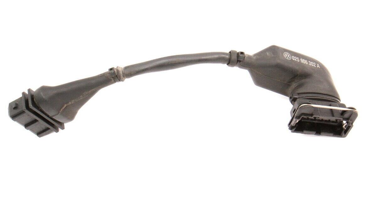
Some airflow sensors can have a vibration resonance of the metering potentiometer wiper during an extended drive at constant speeds. The resonance causes the airflow sensor to supply an intermittent signal to the ECM. The ECM will then default to a "no load" condition and reduce the injection time.
Service:
- Remove harness connector from Airflow Meter (AFM)
- Install converter (signal filter) assembly, Part No. 025-906-302A, between harness and AFM
- CAUTION: Part numbers are for reference only. Always check with your Parts Department for the latest parts information
TSB number: 93-10
Date issued: December 15, 1993
Subject: Digifant engines, 1990-1993
Problem: Rich engine running condition
Condition: A rich engine running condition may be caused by an improper or loose Engine Control Module (ECM) and Oxygen Sensor (02S) Ground (GND) connection.
Service:
- Check the Ground (GND) connection on the engine at the coolant flange mounting stud
- Ensure that the coolant flange mounting stud is installed tightly in cylinder head, tighten if necessary to 87 in.lb. (10 Nm)
- Ensure Ground (GND) connection on stud is clean and tight; clean and tighten connection as necessary
TSB number: 94-01
Date issued: January 20, 1994
Subject: All engines, 1980-1993
Problem: Poor driveability
Condition: Poor driveability may be caused by magnetic interference due to a deteriorated Oxygen Sensor (O2S) wire shield or improper Oxygen Sensor (O2S) wire shield Ground (GND) connection.
Service:
- Check the O2S wire for damage and proper GND connection; replace O2S wire harness and/or clean and tighten Ground (GND) connection as necessary
- If Oxygen Sensor (O2S) wire and Ground (GND) connection appear to be OK, remove Oxygen Sensor (O2S) wire from Engine Control Module (ECM) harness connector, see appropriate wiring diagram for proper connector pin number
- Test drive vehicle; if driveability condition is eliminated, replace O2S wire harness
- O2S wire harness for heated, 3-wire O2S: 701-971-108
- O2S wire harness for unheated, 1-wire O2S: 443-971-108A
- CAUTION: Part numbers are for reference only. Always check with your Parts Department for the latest parts information
TSB number: 93-04
Date issued: November 15, 1993
Subject: Digifant I, Digifant II
Problem: Poor idle/Stalls, Loss of Power, Exhaust Smoke, MIL/CEL on
Condition: A driveability problem can lead to the replacement of the Engine Coolant Temperature (ECT) Sensor when it in unnecessary to do so.
The following observations can lead to a suspected faulty ECT Sensor:
- VAG 1551 Scan Tool indicates ECT Sensor is faulty
- Malfunction Indicator Light (AKA check engine light) is on
- Vehicle loses power
- Excessive visible exhaust smoke
- Stalling and poor idle
- Incorrect, disconnected or faulty wiring
- Corroded terminals
- Faulty input to Engine Control Module (ECM)
- Determine if problem is ECT Sensor related
- Check for correct connections at the ECT Sensor
- Check ECT Sensor wiring for damage
- Check that Ground connections are clean and make good contact
- Check ECT Sensor terminals (tin-plated) and clean with VW contact cleaner, Part No. G00070004, or equivalent
- Check that terminals are properly installed in wiring connectors. Use appropriate wiring diagram
- Use VAG 1598 and digital multimeter Fluke 83 (US 1119) to check resistance of ECT Sensor circuit when engine is cold and again when engine is hot.
- Road test vehicle to check performance.
- Check DTC Memory
- Replace ECT Sensor if necessary
- Road test vehicle
- If no improvement, replace ECM
- Road test vehicle
Fuel System
TSB number: 93-02
Date issued: June 15, 1993
Subject: Digifant engines, 1990-1993
Problem: Faulty knock sensor
Condition: Here are some tips to follow if you suspect that a driveability problem is being caused by the knock sensor system.
Knock sensor malfunction may cause the following symptoms:
- Vehicle appears to lose power
- Increased fuel consumption
- Malfunction Indicator Lamp/CEL comes on
- VAG 1551 Scan Tool indicates knock sensor malfunction
- Incorrect or disconnected wiring
- Corroded terminals (from mismatched terminal material)
- Knock sensor shielding damaged
- Improperly torqued knock sensor mounting bolt
- Abnormal noises caused by
- torn or loose brackets
- loose wiring
- loosened engine components
- broken, loose or missing bolts
- mechanical damage
Service: To avoid making unnecessary repairs, use the following steps when diagnosing suspected knock sensor problems.
- Analyze the problem to determine if it could be knock sensor related.
- Check for abnormal noises caused by:
- torn or loose brackets
- loose wiring
- loosened engine components
- broken, loose or missing bolts
- Check knock sensor installation torque. Loosen knock sensor bolt and torque to: 20 to 25 Nm (15 to 18 lbs.ft.)
- NOTE: Be sure to use a torque wrench that reads accurately in this range.
- Check that knock sensor is connected to the proper wiring harness. (If necessary, refer to Campaign Circular QX)
- Check that the knock sensor wires are not damaged.
- Check knock sensor terminals for correctly matched material. If the knock sensor terminals are tin-plated, the mating connectors must be tin-plated. If the knock sensor terminals are gold-plated, the mating connectors must be gold-plated. If the terminals are not the same material, metal corrosion has taken place on the terminals and the knock sensor and terminals must be replaced.
- Check that the terminals have been installed in the connector in the proper position using the latest wiring diagram for the vehicle you're working on.
- Road test the vehicle and check performance.
- If you still suspect a knock sensor problem:
- Check the fault memory (if possible)
- Check the knock sensor wiring at the ECM
- If still no improvement, replace the knock sensor and road test the vehicle again.
- NOTE: Replacement knock sensors only have gold-plated terminals. Earlier original equipment sensors have alloy plated terminals. Both the make and female terminals of the knock sensor connection must be of the same material.
TSB number: 93-06
Date issued: November 15, 1993
Subject: Digifant I and II, 1990-1993
Problem: Hunting Idle
Condition: After initial cold starts, the idle speed hunts for approximately one minute. After this period, the idle speed returns to normal.
Idle hunting is an indication of a properly functioning idle air control system trying to compensate for varying fuel/air mixtures.
Proper fuel/air mixture is required at all phases of operation. Idle hunting is in many cases caused by improper fuel mixture during the initial start-up phase. The Idle Air Control (IAC) Valve attempts to compensate for a low RPM by opening wider, increasing the air flow and in turn increasing the fuel injection time. When the mixture burns completely, the RPM will increase and the IAC will close. Idle hunting is due to the rapid opening and closing of the valve.
Replacing the Idle Air Control (IAC) Valve will not resolve this condition. To ensure proper diagnosis and replacement of the IAC valve, you must get prior repair authorization from your Warranty Adjuster or your DSM.
Service:
- First verify that the IAC system functions properly by checking the idle stabilization system, see Repair Manual, Repair Group 24.
- Check fuel injectors and intake valves for carbon deposits. If necessary perform cleaning procedure as described in brochure: "Solving Driveability Complaints", No. WSP 521 154 00.
- Perform diagnostic and troubleshooting procedure as described in brochure: "Solving Driveability Complaints"
Ignition, Starter
TSB number: 92-02 (supersedes TSB 91-01)
Date issued: February 29, 1992
Subject: 010 Automatic Transmission
Problem: Does Not Engage/Restart When Engine is Hot
Condition: Starter motor does not engage during restart when engine is hot.
The starter motor is heated up by the engine. During cranking, the voltage at terminal 50 of the starter solenoid must be at least 10 Volts. This value will not be reached at times by older vehicles.
Service:
- Check battery power and ground connections to engine / transmission and connection to starter motor for tightness and corrosion. Repair if necessary.
- If all connections are in order, or if repair of connections does not correct the condition, install starter relay to activate the starter solenoid as follows:
- (Lengthy original TSB instructions omitted here. Please refer to the DIY guide.)
TSB number: 93-10
Date issued: December 15, 1993
Subject: Digifant engines, 1990-1993
Problem: Rich engine running condition
Condition: A rich engine running condition may be caused by an improper or loose Engine Control Module (ECM) and Oxygen Sensor (02S) Ground (GND) connection.
Service:
- Check the Ground (GND) connection on the engine at the coolant flange mounting stud
- Ensure that the coolant flange mounting stud is installed tightly in cylinder head, tighten if necessary to 87 in.lb. (10 Nm)
- Ensure Ground (GND) connection on stud is clean and tight; clean and tighten connection as necessary
Interior
TSB number: 91-02
Date issued: November 30, 1991
Subject: Seat Cover Beading
Problem: The lower seat cover beading is supported by a flexible plastic piping. This piping slowly slips out of the beading and becomes visible.
Service: Cut visible plastic pipe off. Then glue the beading openings closed.
- NOTE: Seat covers should only be replaced if more than 150 mm of pipe is visible.
TSB number: 92-01
Date issued: April 30, 1992
Subject: Defroster Vents, 1990-1991
Production: Production assembly modified as of 02/91, VIN 15MK020420
Problem: Vinyl coming loose from the dashboard around the edges of the defroster vent openings may affect the direction of air flow.
Service: In case of customer complaint of inadequate defroster function, install plastic inserts into the defroster openings. Part No. 171-857-461C Qty. 2 and Part No. 171-857-461B Qty. 4
- CAUTION: Part numbers are for reference only. Always check with your Parts Department for latest parts information.
Suspension & Steering
TSB number: 90-03 (supersedes 89-02)
Date issued: September 30, 1990
Subject: CV Joints - all models
Problem: Revised diagnosis, inspection and replacement
Service: Locating a noisy CV joint:
- Test drive the vehicle.
- Listen for clicking, popping or grinding noises during initial acceleration/deceleration and while turning.
- Noises noticeable during a left hand turn are usually generated by a CV joint on the right hand side and visa versa.
- Check for cut or damaged cv joint boots, resulting in inadequate or contaminated CV joint lubricant.
- Remove axle shaft on the noisy side
- Disassemble and clean both joints
- Check housing, hub, cage, balls of both joints for pitting, burrs or excessive wear.
- Replace joint if any of the above mentioned conditions are apparent.
TSB number: 89-03
Date issued: August 31, 1989
Subject: Power Steering Fluid
Info: Beginning April 1989, the power steering will be filled with hydraulic oil, instead of ATF. It is the same hydraulic fluid used in Audi vehicles.
Part Number: G002000
This hydraulic oil exhibits good viscosity behavior especially during cold temperatures. In countries with cold temperatures, it is recommended after repair work is performed on the power steering that only G002000 be used to refill. This formula can be used on ALL current production vehicles.
NOTE: Hydraulic oil G002000 can be mixed with ATF.
CAUTION: Part numbers are for reference only. Always chock with your Parts Department for latest information.
Transmission - Automatic
TSB number: 91-02
Date issued: May 31, 1991
Subject: 010 automatic transmission
Problem: Shifts Erratically
Condition: Automatic transmission shifts erratic due to leakage between automatic section and the differential section of the transaxle.
Service:
- Remove transmission from vehicle according to sections 37 and 39 of the Repair Manual Microfiche.
- Inspect transmission for damaged components, replace components as required.
- Determine build date of transmission from transmission case.
- During repair and reassembly of transmission, the following additional steps are required:
- On transmissions with build dates prior to 04100: Apply sealant paste, Part No. AKD45610002 to threads of intermediate gear shaft, Part No. 010-409-727.
- On transmissions with build dates of 04100 and beyond: Apply sealant paste, Part No. AKD45610002 to threads of intermediate gear shaft, Part No. 010-409-727, install 0-ring (2), Part No. 010-409-530.
- CAUTION: Part numbers are for reference only. Always check with your Parts Department for latest parts information.
TSB number: 91-02
Date issued: April 30, 1991
Subject: 010 automatic transmission
Problem: Ticking Noises at 1800 to 3200 RPM
Condition: Engine noise may be amplified by the torque converter drive plate.
Service: Install modified drive plate, Part No. 053-105-323E.
- The distance measurement (a) of 31.3 mm + 0.7 mm must be achieved by use of the 4.0 mm washer, Part No. 053-105-301A and/or the 1.0 mm shim, Part No. 056-105-303 for item, to achieve the required 31.3 + 0.7 mm.
- Discard any shims from the old drive plate.
- One and only one 1.0 mm shim (1), Part No. 056-105-303, must be used between drive plate and mounting bolts. Torque to 30 Nm (22 FT.lb.) + 1/4 (90°) turn.
- The torque converter bolts, Part No. 087-323-699, must be secured with locking compound, Part No. D000600. Torque to 35 Nm (26 ft.lb.)
- NOTE: With improved drive plate installed, it is not necessary to install the crankshaft with cross drilled bores or piston rods with inline bores on vehicles produced before:
- 4/88 VIN 15JK024042
- CAUTION: Before removing transmission, set engine to TDC. This ensures alignment of the drive plate to the transmission.
- CAUTION: Part numbers are for reference only. Always check with your Parts Department for latest parts information.
- Refer to the Repair Manual Microfiche, Group 13 for removal and installation procedures.
Transmission - Manual
TSB number: 93-04
Date issued: June 15, 1993
Subject: 020, 02A, O2B manual transmissions
Problem: Difficulty Shifting In and Out of Gear
Condition: Transmission intermittently difficult to shift in and out of gear.
Service: Ensure that the shift linkage and clutch free play is adjusted properly and is not causing the complaint. If the shift linkage is adjusted properly proceed as follows:
- Remove transmission.
- Thoroughly clean main shaft splines with wire brush.
- Use just enough Moly lubricating paste/spray, part number G 000 100, on the main shaft splines to allow the clutch disc to slide freely.
- Slide the clutch disc back and forth a few times on the main shaft and then wipe off any excess lubricant.
- CAUTION: If too much is applied, excess lubricant will end up on the clutch disc face causing the disc to stick to either the pressure plate or the flywheel. This will cause difficult shifting and/or grinding into gear.
- CAUTION: Only install clutch discs with nickel-plated hubs. These clutch discs can be identified by the color of the hub. The hubs have a shiny stainless steel like appearance. Earlier version clutch disc hubs are phosphate coated. The hubs on these discs have a flat gray or black appearance and must not be used.
TSB number: 40-90 T01
Date issued: May 31, 1990
Subject: 020 transmissions
Problem: Flanges on Remanufactured Transmissions
Service: Remanufactured transmissions are assembled with either 90 mm or 100 mm flanges. When you replace a transmission with a rebuilt unit; do not replace drive shafts to match to the flanges. Instead replace the flanges to match to the drive shafts.
In case of replacement, remove the new flanges from the rebuilt unit and exchange them for new flanges that match the existing drive shafts. Your Parts Department will provide you with the exchange flanges. Also, please remember to use new flange seals.
TSB number: 87-01
Date issued: July 31, 1987
Subject: 020 transmissions
Problem: Grinds into 1st/Reverse/Hard shifting - clutch disc binding
Service: Grinding when shifting into 1st or reverse may be due to incomplete clutch disengagement caused by the clutch disc binding on the mainshaft.
When installing a clutch disc, thoroughly clean splines of disc and mainshaft with a wire brush and lubricate with MOS2 grease, Part Number G000602. Ensure disc slides freely on shaft before assembly.